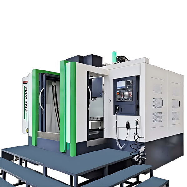
A horizontal machining center is a high-precision CNC machine tool with a horizontal spindle arrangement, multi-axis linkage and automatic tool change functions, and is particularly suitable for efficient processing of complex parts. It is widely used in aerospace, automobile manufacturing, mold manufacturing and other fields, and can easily handle large workpieces and achieve multi-faceted processing. It is particularly suitable for complex processing of multi-faceted parts such as milling, drilling, boring, reaming, tapping, and two-dimensional and three-dimensional surfaces. Compared with vertical machining centers, horizontal machining centers have more advantages in chip removal and stability, and are particularly suitable for scenarios with large-scale production and high-precision requirements.
Horizontal machining centers refer to machining center machine tools with the spindle axis parallel to the worktable.
It can process larger parts and can be indexed and rotated. It is most suitable for multi-process machining of parts with multiple working surfaces, such as milling, drilling, boring, reaming, tapping, and two-dimensional and three-dimensional surfaces.
It has the ability to complete the box in one clamping.
It has good performance in body hole systems, and plane processing is especially suitable for turning and boring box body holes, and is widely used in automobiles, internal combustion engines, home appliances, general machinery, and other industries.
Dual-Pallet Horizontal Machining Center in Action
A horizontal machining center (HMC) can easily move the spindle head and the table in a horizontal direction. This helps to achieve a greater degree of accuracy while machining the component parts with the help of the cutting tools.
The Horizontal machining center also allows for high productivity as the spindle head and the table can move independently and handle the workpiece in the vertical direction and simultaneously machining of multiple workpieces, allowing for faster processing and production time.
The Horizontal machining center can be equipped with more tools, and more work can be done in one process, offering higher versatility as the cutting tool can be changed quickly and the machine can accommodate a range of workpieces with different shapes and sizes.
With the help of the CNC programming feature, the machine is also able to accurately repeat the same machining operation on multiple parts. All these features make the Horizontal machining center the ideal machine for the production of high-quality parts in the most economical way possible.
Furthermore, the Horizontal machining center is designed for improved tool life and higher accuracy when compared to conventional machines. With the help of advanced features like the servo motor control system, the machine can maximize the cutting time and the accuracy of the parts produced.
All these features make the Horizontal machining center the right choice for the mass production of precision parts with the best quality.
Therefore, the Horizontal machining center makes it the ideal choice for high-precision jobs. It is perfect for meeting the requirements of even the most demanding tasks. It is the perfect machine for the modern manufacturing plant.
The horizontal machining center is divided into fixed column type and mobile column type according to whether the column moves.
1. The worktable moves in a cross direction, the worktable moves in the X and Z directions, and the spindle box moves in the Y direction. It is suitable for multi-process processing such as boring and milling of medium-sized and complex parts.
2. The headstock moves crosswise, the headstock moves in the X and Z directions, and the worktable moves in the Y direction. It is suitable for multi-process processing such as boring and milling of small and medium-sized parts.
3. The spindle box is hung on the side and the column, and the spindle box moves in the Y and Z directions. This layout is similar to the planer-type horizontal milling and boring machine, and the worktable moves in the X direction. It is suitable for multi-process processing such as boring and milling of medium-sized parts.
The bed is T-shaped, the worktable moves in the X direction on the front bed, and the column moves in the Z direction on the back bed. The spindle box has two forms of positive hanging and side hanging on the column, moving in the Y direction. It is suitable for multi-process processing, such as boring and milling of medium and large parts, especially parts with large lengths.
The column moves in Z and U (parallel to the X direction), the spindle box moves in the Y direction on the column, and the worktable moves in the X direction on the front bed. It is suitable for multi-process processing, such as boring and milling of medium-sized and complex parts.
the spindle box moves in the Y direction on the column, and the spindle ram moves in the Z direction. The column moves in the X direction. The table is fixed or equipped with a rotary table. It can be equipped with multiple worktables, which is suitable for the processing of small and medium-sized parts, and the workpiece loading and unloading and cutting times can be coincident.
| NO.: | Differences | Horizontal Machining Center HMC | Vertical Machining Center VMC |
| 1 | Spindle | Horizontal spindle running parallel to the worktable’s surface | Vertical head runs perpendicular to the worktable’s surface |
| 2 | Workbench | The table of the horizontal machining center only moves in the X or Y direction. The table is generally a rotary table with a lattice screw hole table, and it is relatively easy to choose an exchangeable double table. | Generally a T-slot worktable with a cross-slide structure. There are two sets of motion mechanisms responsible for the movement of the worktable in the vertical direction. |
| 3 | Column | HMC's column is a moving column. The column of the positive T type moves along the X direction, and the column of of the inverted T type moves along the Z direction. The structure of the mobile column requires that the column must be as light as possible under the premise of satisfying rigidity. | VMC's column generally does not move and made as thick as possible in order to pursue rigidity. There are also moving-column vertical machining centers. The table of the moving-column vertical machining center only moves in the X or Y direction, and the column moves in the Y or X direction accordingly. This design method has greater power requirements for the drive motor of the column. |
| 4 | Cutting Tools | Shorter and thicker tools capable of taking deeper cuts and removing more material | Long cylindrical tools (end mills) for more precise but shallower cuts on smaller workpieces. |
| 5 | Control System | The workpieces processed by the horizontal machining center are generally relatively large, the clamping is difficult, it is not easy to monitor the processing process, and the operation and debugging is relatively difficult. | The vertical machining center is easy to clamp, easy to operate, easy to observe the processing situation, and easy to debug the program. |
| 6 | Cutting Specifications and Accuracy | Have better stability for deep, heavy cuts | Vertical tooling cannot do deeper cuts, no good at the accuracy of the deep cut |
| 7 | Versatility | General | Better, can be boring mills, drill press, can face and slot, more adept at prototyping, custom work, and engraving |
| 8 | Structural complexity | More complexity | Less complexity |
| 9 | Cost of Machine, Operation and Maintenance | More expensive, 2-3 times. | Cheaper, and can be better small shop |
| 10 | Material Removal Rate | Much higher material removal rate | Less material removal rate |
| 11 | Overarm and Arbor Support | Have Overarm and Arbor Support | No Overarm and Arbor Support |
| 12 | QTY of Faces for Machining | 4 faces and at several angles | Only 1 face, and 1 angel. |
| 13 | Chip Evacuation | Better at chip removal | More metal chips remain on the vertical mill’s workpiece surface |
| 14 | Operating Difficulities | More complexity and fewer HMC and less trained operators. | Easy and more trained operators to find |
| 15 | Processing Workpieces Material: | Suitable materials for processing: such as 45# steel, aluminum alloy, copper, aluminum, stainless steel, iron, composite materials and other materials. | Suitable materials for processing: such as 45# steel, aluminum alloy, copper, aluminum, stainless steel, iron, composite materials and other materials. |
| 16 | Processing Workpieces Size: | Can process bigger parts | Cannot process parts that are too high and relatively smaller size. |
| 17 | Processing Workpieces Shape: |
HMC is most suitable for processing large-scale box-type workpieces. It mainly performs hole system processing and plane processing on box-type workpieces. One-time clamping of the workpiece can complete the processing of other surfaces except the mounting surface and the top surface, and its rotary shaft is installed on the worktable to rotate the workpiece to process all sides of the workpiece. It is also possible to install multiple rotary axes for joint movement, so as to process complex curved surface type box parts. |
Box parts: parts with more than one hole system, a cavity inside, and a certain proportion in the length, width, and height directions. Such parts are widely used in industries such as machine tools, automobiles, and aircraft manufacturing. Complex curved surface parts: various impellers, wind deflectors, spherical surfaces, various curved surface forming dies, propellers and propellers of underwater vehicles, and some other shapes of free curved surfaces. Disc, sleeve and plate parts: Disc sleeves or shaft parts with keyways, or radial holes, or distributed holes on the end surface, curved surfaces, such as sleeves with flanges, shafts with keyways or square heads Parts, etc., as well as plate parts with more hole processing, such as various motor covers, etc. Special processing: Assemble certain tooling and special tools to complete special craft work, such as engraving, engraving, and engraving patterns on the metal surface; install a high-frequency electric spark power supply on the spindle of the machining center to perform line scanning on the metal surface surface hardening. |
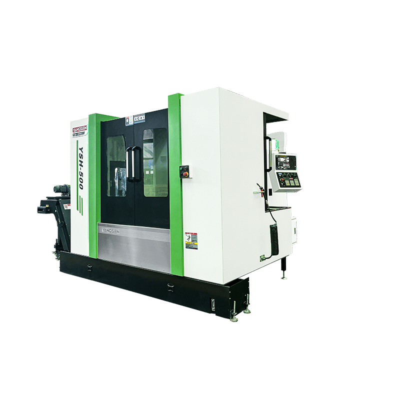
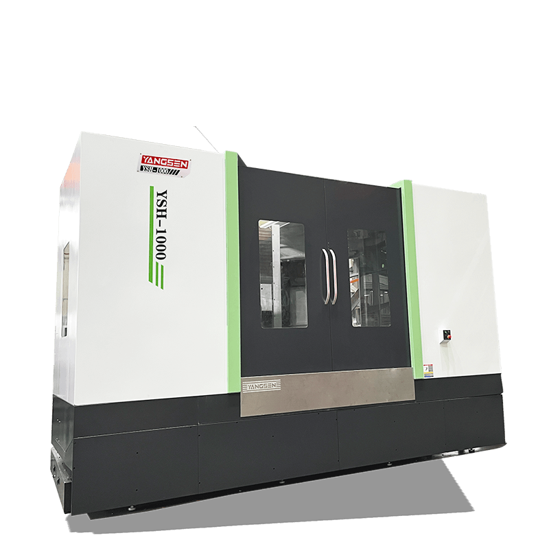
YSH series installs T design, worktable rotating structure form, ultra-wide guide guideway structure, the standard configuration of large torque, and high-speed motor. You could order an exchange worktable separately. Our products are suitable for processing various complex parts. It is the preferred equipment in the field of automobile engines and cavity processing in the 5G field.
Product Overview:
T-structure bed: Enhanced long-term accuracy (±0.005mm retention); reduced moving inertia for high-speed precision.
X-axis differential-height rails: Lowered column CG improves counterforce resistance; boosts boring accuracy.
Optimized for: High-tolerance batch production of complex box-type parts and structural components.

YSH Horizontal Machining Frame Machine Characteristics:
 |
Machine bed, Column An equilateral triangle structure of the column, with multi-layer stiffeners, is arranged to improve the stability of the machine bed. Positive T structure bed, X-axis stepped layout, enlarged line guideway span, rigid support. Adopt a high-strength Rexroth roller guide, high load bearing, stable precision. |
 |
Spindle install 6 high-rigidity bearings; Outer diameter 190mm Taiwan original BBT50 spindle; Spindle air blow to prevent object from entering the spindle; The spindle is equipped with ring spray to improve processing quality. The standard FANUC large-torque wide-area motor β ilP30/8000 is equipped with stronger heavy cutting ability. |
 |
Optical Linear Scales Optional Heidenhain, Fagor Optical Linear Scales, accuracy ± 5um, to ensure machine tool positioning accuracy. |
 |
Double exchange table/ four-axis turntable Realize workpiece exchange and improve processing efficiency; The workpiece is placed outside for easy clamping; High rigidity alloy turbine, wear-resistant, high positioning accuracy; Heavy locking, reduce deformation, resistant to heavy cutting. |
 |
Tool magazine Using Taiwan imported frequency conversion tool magazine, tool change speed is fast and stable. |
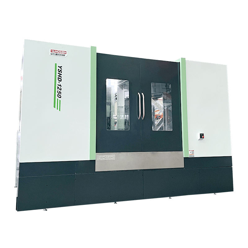
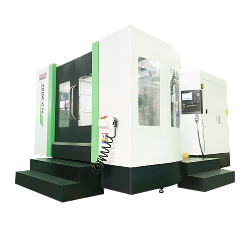
Product Overview:
Inverted T-column design: Large-part machining & indexing capability.
Multi-process operations: Milling, drilling, boring, tapping, 2D/3D contouring.
Industries: Automotive, Aerospace, Appliances, General Machinery.

YSHD-630 Opto-Mechanical Characteristics:
|
Bed Structure Inverted T-base with FEA-optimized M-ribbing (static rigidity ≥250 N/μm) Rotary Table High-rigidity Ni-Cr alloy copper worm gear Triple-clutch gear: ±2 arc-sec indexing Precision Optional Heidenhain Fagor encoders (±5μm) ATC Options Hydraulic swing-arm ATC 24/40/60-tool magazines Spindle BBT50 spindle (190mm Ø, Taiwan): 6 high-rigidity bearings Labyrinth nose air purge High-torque motor (6000 rpm) |
 |
Machine Cutting Performance
|
Surface Milling |
Steel 45# |
Drilling Holes |
Steel 45# |
Tapping |
Steel 45# |
|
Cutting depth 7mm |
|
Cutter diameter Ø82 |
|
Tapping M36 |
|
|
Cutter |
Ø120mm*5T |
Cutter |
Ø82mm*2T |
Cutter |
M36*3P |
|
Spindle speed |
420rpm |
Spindle speed |
500rpm |
Spindle speed |
120rpm |
|
Feed |
F500 |
Feed |
F100 |
Feed |
F480 |
|
Width |
100mm |
Width |
82mm |
Width |
36mm |
 |
 |
 |
 |
| Cylinder Block | Pump Body | Gear Box Housing | Hydraulic Control Valve |
|
Arm Type Tool Changer
Automatic Lubricating System
Fully Enclosure Guard
|
Rigid Tapping
Heat Exchange for Electric Cabinet
Coolant Tank & Chip Tray
|
Daul LED Work Light
LED 3 Color Warning Light
M30 Auto Off
|
Spindle Nose Air Blow
Leveling Bolts and Pads
|
|
Optical Linear Scale
CTS
|
Tool Breakage System
Chain Type Chip Conveyor System
|
Oil Mist Collector
Oil Skimmer
|
Rotary Table
Workpiece & Tool Probe
|
YSH Series:
| Model | YSH-630 | YSH-800 | YSH-700D | YSH-800D |
| Travel X/Y/Z mm | 1300/800/1000 | 1300/800/1000 | 1300/800/9000 | 1300/800/1000 |
| Working Table LxW mm | 630x630 | 800x800 | 700x700 Duplex | 800x800 Duplex |
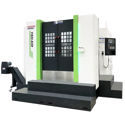
YSHD Series: inverted T Shape
| Model | YSHD-630 | YSHD-1000 | YSHD-1250 | YSHD-1250D |
| Travel X/Y/Z mm | 1100/750/950 | 2000/1500/1600 | 2000/1500/1600 | 2000/1500/1600 |
| Working Table LxW mm | 630x630 | 1000x1000 | 1250x1250 | 1250x1250 Duplex |
For more information, please click the above items