Why does a high-tech store come to a standstill when one important machine goes down? Each minute of spindle downtime costs profit and puts a load on delivery commitments. A 3-axis mill or a turning center may cost hundreds of dollars to possess and use an hour.
Downtime is expensive once it stretches. The positive side of the story is that a majority of failures have predictable patterns. Provided you can learn those patterns and behave consistently, you can bring production back within hours rather than days.
This guide provides you with the complete map of CNC machine troubleshooting. You will discover the reasons, repair the defects, and prevent the recurrence of problems. The CNC Vertical Machining Center from Yangsen keeps tight tolerances even in long production runs.

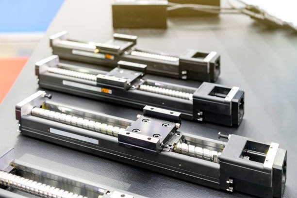
A machining center is mounted on a heavy cast-iron or steel base. The base is vibration-damping and supports the guideways, which allow the table to travel along X, Y, and Z. Ball screws are attached to each axis motor and allow the table or head to move via rotary motion to straight motion. The slide is kept in line by linear guides or box ways.
The machine is centered around the spindle. It picks up the tool, rotates at a high speed, and has to remain stiff. A common spindle is a ceramic or steel bearing filled with grease or supplied with an oil-air mixture. An ATC, or tool changer, changes tools without the assistance of the operator. On a mill, it may be a carousel or a chain. It is commonly a turret on a lathe.
Lock out power. Turn off the main breaker and hang a lock. Drain air from the lines. Post a tag that warns others not to start the machine. Do not rely on the control’s E-stop alone. Yangsen’s Horizontal Machining Center lets you cut several faces in one setup and still hold size.
● Look and listen. Loose wires, burnt smells, dripping coolant, or chipped paint often point to trouble spots.
● Check the control’s diagnostics page. Record voltage, axis load, spindle load, oil pressure, and air pressure.
● Note all active and past alarms. Many controls store the last 100 alarms; scroll through them to spot patterns.
A formal method beats guesswork. The 5 Whys works well:
1. Why did the axis stop? Because a servo drive alarm tripped.
2. Why did the alarm trip? Because the current spiked.
3. Why did the current spike? Because the slide jammed.
4. Why did it jam? Chips are packed in the way covers.
5. Why did the chips pack? Because covers were torn and not replaced.
Write down the date, symptom, root cause, parts used, and time spent. A simple log helps the next tech solve the same fault faster. It also shows patterns that may signal a design flaw or training need.
|
Fault |
Symptom You See |
First Check |
Likely Fix |
|
No Power-Up |
Screen dark, no lights |
Main breaker and fuses |
Reset the breaker or replace the blown fuse |
|
Random Reboots |
Control restarts during cuts |
Measure line voltage |
Stabilize power or install a UPS |
|
Axis Overload Alarm |
The axis stops with a loud buzz |
Chips under way covers |
Clear chips and lube guides |
|
Spindle Overheat |
Nose too hot to touch |
Check coolant flow |
Clean filters and restore flow |
|
Poor Surface Finish |
Visible lines on the part |
Holder runout |
Replace or balance the holder |
|
Tool Breakage |
Cutter snaps mid-cut |
Feed and speed values |
Reduce rpm, raise feed per tooth |
|
Position Drift |
Size grows throughout the day |
Ball-screw temp rise |
Clean lube lines and flush oil |
|
Stuck Tool In Spindle |
The drawbar will not release |
Air pressure gauge |
Raise pressure or fix the leak |
|
Encoder Error Alarm |
Axis won’t be home |
Loose shield ground |
Tighten or replace the cable |
|
Low Clamp Pressure |
Pallet changer stalls |
Hydraulic level sight-glass |
Top up oil and bleed air |
CNC controls need a stable voltage within ±5 %. Use a true-RMS multimeter to read each leg. If one leg sags, drives may reset, or the control may lock up. Check the plant feed, then look for loose lugs in the main box. Replace worn breakers and consider a voltage stabilizer if utility power swings often.
Inspect power cables for cracked insulation. Heat marks under a lug show a loose connection. Tighten to the torque value the maker lists. A missing ground lets noise flow into the control and makes random faults hard to trace. Measure resistance from the machine frame to the plant ground; it should be below one ohm.
If the E-stop circuit will not clear, trace each switch and relay with a meter. Water or coolant inside a door switch can short the contacts. Replace cheap plastic E-stop buttons if they stick. On older machines, the relay coil may fail; swap with a known good part.
● Surge suppressors on all phases guard drives from lightning hits.
● A small uninterruptible power supply keeps the control alive long enough to park the axes in a power loss.
● Label every breaker and fuse so night-shift techs can act fast.
Mount a pocket-size vibration meter on the spindle housing. Compare readings to the maker’s specs. High vibration often traces to:
● Imbalance: Tool holders not balanced for high rpm.
● Loose belts: Worn or slack belts slap the pulleys.
● Bearing wear: Pitted balls or races create a growl.
Correct imbalance by using balanced holders and pulling chips out of coolant nozzles. Tighten or change belts. If bearing noise stays loud, pull the spindle for rebuild before runout ruins parts. When large parts need heavy cuts, the Gantry Machining Center gives you the stiffness and reach to stay on spec.
Sweep a test indicator across the spindle nose to check tram. If the reading changes more than 0.0008 in, shim the head. For backlash, move an axis by command and watch a dial indicator at the table. If motion starts late or stops early, backlash is high. Adjust ball-nut preload on small machines; on large machines add pitch error compensation in the control.
Touch the spindle nose. It should feel warm, not hot. A 30 °F rise over room temperature is a warning. Check cooling flow, belt tension, and tool load. On grease-packed bearings, too much grease can also cause heat. If temperature climbs despite good flow, plan a bearing change.
Ball screws need a thin oil film. If lube lines clog, the screw runs dry and wears fast. Remove lines, flush with clean solvent, and purge with new oil. Replace wipers every six months so chips stay out.

Use a 10× loupe. Normal flank wear shows as a shiny land on the edge. Chipping means the edge breaks in small chunks. Breakage is a full snap. Causes include:
● Speed too high for the carbide grade.
● Feed too light so the tool rubs instead of cuts.
● Interrupted cuts that shock the edge.
Slow the spindle by 10 %, raise feed by 5 %, and use a tougher grade if chipping repeats. Always push chips away with coolant.
Runout tears metal. Measure radial runout with a tenths indicator. If above 0.0002 in, clean the taper, change the pull stud, or discard the holder. If finish still looks dull, add a second roughing pass so the finish tool sees a uniform chip load.
Calculate surface footage (SFM) and chip load before you press cycle start. A ½ in end mill in 6061 aluminum often likes 800 SFM and 0.004 in per tooth. For slotting, cut feed in half. Use a feed and speed chart or an online calculator; do not guess.
Stringy chips wrap tools, hold heat, and scratch walls. Program a peck cycle on drills deeper than three diameters. Add through-tool coolant or air blast. Clean filters in the coolant tank weekly; many shops skip this simple task.
A missing decimal in X0.1 turns into X1.0 and wrecks work. Always back-plot the code in the CAM package. Then run the first part above the stock with single block and rapid override at 5 %. Watch every line.
Each control needs a post that matches its syntax. A Fanuc post may send codes the machine understands, yet a Siemens or Mazak control will misread them. Keep post library up to date. Verify after every major CAM update.
Set work offsets with a probe when you can. Manual edge finders work, but mistakes happen. After homing, jog each axis to limit and listen for a smooth stop. If it hits hard, home position needs adjustment. Some controls let you re-establish grid shift with a simple menu.
Back up parameters, macro variables, and programs to a USB stick every week. Store a second copy off-site. If memory gets scrambled, you will thank yourself for five minutes of extra work.

A servo alarm often means overcurrent or overvoltage. Check the drive’s LED code. Most makers print the meaning on the drive cover. If the current is high, look for a jammed axis or a shorted motor cable. If the voltage is high, the regen resistor may be open.
Encoders send position through shielded cables. Loose shields act like antennas. Route motor power and encoder lines in separate conduits. Replace oil-soaked connectors. If errors appear only when coolant runs, look for wicking at the cable ends.
The control sends a target path. If the axis lags by more than the error limit, the drive faults. Causes include dry ways, worn couplings, or low servo gain. Grease the way surfaces, tighten couplings, then run an auto-tune routine if the control offers one.
After a motor or drive change, run a step test. Watch the position plot. A good tune reaches the command fast, stops without bounce, and stays flat. Increase proportional gain in small steps until a slight overshoot appears, then back off. Add integral gain to remove steady-state error. Document final values.
A drawbar stuck with a half grip often points to low air. Read the regulator. It should match the pressure on the spindle spec sheet, often 85 to 90 psi. Replace filters that show rust or water. Use air dryer units in humid climates. High-speed hole making is easy with the CNC Drilling Machine, built for short cycles and clean chips.
Hydraulic clamps need time to reach the set pressure. If a pallet changer stops mid-swing, check the slow-vent valve. If oil looks milky, water has mixed in. Change oil and fix the breather.
Change air filters every 1,000 cutting hours. Mark each change on the body with a paint pen. Check regulators for creep; if the outlet pressure drifts up when flow stops, the seat leaks. Replace the regulator before it ruins seals downstream.
Most controls rate electronics life at 95 °F. Above that, capacitor life falls. Install a small cabinet air conditioner if the shop often sees high heat. In cold shops, condensation forms when machines warm up. Leave the spindle fan running after shutdown to dry the moisture.
A forging hammer, punch press, or even a busy aisle can shake a high-precision mill. Check vibration with a floor seismometer. Pour a separate pad or add rubber isolators if levels exceed maker limits.
Crash logs show that a new hire often triggers the first collision within 90 days. Use a “shadow day” where a trainee watches a seasoned operator write offsets and load tools. Run skill refreshers each quarter. A confident operator sees small problems early. The Engraving and Milling Machine combines fine detail work with strong metal-removal power in one unit.
Attach accelerometers to the spindle, bearings, and motor. Trend readings. A rise in overall velocity or a spike at a bearing pass frequency warns you months in advance. Schedule repair instead of reacting.
A handheld infrared camera marks hot spots in motors, breakers, and bearings. Shoot images once a month. A new hot spot larger than two square inches means action now.
Send spindle oil samples to a lab. High iron counts show wear. Water content should stay below 500 ppm. For coolant, keep concentration within the range the maker lists, often 6 % to 10 %. Track pH; low pH rusts ways, high pH harms skin.

Modern controls stream data over Ethernet. Dashboard software records uptime, feed rates, and alarms. It highlights repeat faults so you focus on high-value fixes. Some systems send text alerts so the night shift can respond fast.
● Daily: Wipe windows, clear chips, check oil level, drain water from the air line.
● Weekly: Clean coolant tank filters, test spindle fan, inspect way wipers.
● Monthly: Pull vibration data, back up programs, and verify the axis square with a granite square.
Post checklists near the machine. Sign and date each line. Managers can scan logs to see gaps.
Store drive belts, fuses, limit switches, a spare fan, and one servo amplifier. Label each part with machine model and parameter set if needed. First-in, first-out rotation stops parts from aging on the shelf.
After every failure, gather the crew. Ask three questions:
1. What failed?
2. Why did it fail?
3. How do we stop a repeat?
Update standard worksheets. Train staff on the change and mark the revision date.
CNC machines mix tight mechanics, smart software, and fine electronics. Each element can fail, yet each leaves clear clues for the trained eye. Work safely, gather facts, trace the root cause, fix, then log the lesson learned. Combine basic housekeeping with modern predictive tools, and you will turn crashes into rare events.