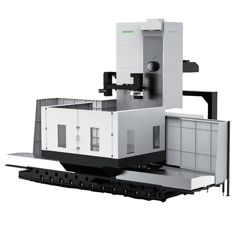
Horizontal boring machines are designed for heavy-duty machining, deep hole boring and high-precision milling of large workpieces. They are mainly used for precision machining such as drilling, boring, milling and tapping. They are suitable for machining complex structural parts such as boxes, frames and molds.
A horizontal boring machine is the most widely used type of boring machine. It is mainly hole processing, and the boring accuracy can reach IT7.
It is also called horizontal boring mills. In addition to enlarging the cast or processed holes on the workpiece, the horizontal boring machine can also mill the plane, drill, process the outer circle of the end face and the flange, and cut the thread. etc.
High precision: you can also use the machine in small batch production and repair workshops, the roundness error of the processing hole is not more than 5 microns, and the surface roughness is Ra0.63-1.25 microns.

Primary Operations: Precision milling & boring; secondary: drilling, reaming, facing, OD turning.
Specialisation: Multi-bore systems & box-type components requiring exact bore spacing.
Industrial Applications: Metallurgy · Energy · Shipbuilding (multi-process: boring /milling /drilling.
The boring machine with the main shaft is arranged horizontally and the headstock can move vertically along the guide rail of the front column. When using a horizontal boring machine for processing, the tool is installed on the main shaft, boring bar, or flat rotary table, and various speeds and feeds can be obtained through the main shaft box, and at the same time, it can move up and down along the guide rail of the front column with the main shaft box.
The workpiece is installed on the workbench. The workbench can move vertically and horizontally with the lower slide and the upper slide, and can also rotate around the circular guide rail of the upper slide to the required angle to adapt to various processing situations. When the boring bar is longer, one end can be supported by the tailstock on the rear column to increase the rigidity.
In order to process workpieces (large components) with large hole distances or long boxes, some horizontal boring machines increase the horizontal stroke of the worktable by about two times and increase the stiffness of the lower seat by increasing the width of the main rail of the bed and the auxiliary guide rail.
Horizontal Boring Machining Center Structure Characteristics:
 |
1. Tool magazine structure 40 and 60 tools guideway-type tool magazines, which are driven by a servo tool magazine, improve the overall tool change efficiency. |
|
2. Spindle structure The main shaft installs European structure design, high rigidity, high speed, and low vibration. Low speed and high torque for the spindle. |
|
| 3. The worktable installs super-large grinding gears. It is combined with twin-turbo, vortex anti-backlash structure to ensure accuracy. | |
|
4. Transmission structure The X and Z-axis transmission method installs a direct-acting four-wheel drive. It has stable accuracy. Also, it could eliminate backlash, and improve torsional rigidity and allow angle. The Y-axis installs direct-drive transmission and cooperates with a German reducer to improve torsional rigidity. |
|
|
5. Counterweight structure Use servo frequency conversion hydraulic station, the counterweight of the hydraulic cylinder reduces the axial load and lengthen the life. |
|
|
6. Casting structure design The linear guideway installation surface and the ballscrew center are on the same plane, which makes the ballscrew drive more stable and ensures the stability of the overall accuracy of the machine tool. |
|
|
7. Hanging guideway structure The Y-axis adopts a box-in-box high-rigidity right and left paired lining structure. The Y-axis installs 4 linear guide guideways, 2 front and 2 back, with high rigidity, high precision, and long service life. |
In-House Sheet Metal Fabrication Workshop:
YANGSEN has invested in and built its own full-scale sheet metal workshop. By controlling our sheet metal production in-house, we are able to significantly shorten lead times, ensure precise fabrication quality, and respond quickly to custom job requirements.
Why our own sheet metal workshop matters:
Faster Lead Time: Eliminate outsourcing delays and accelerate delivery of finished machines.
Improved Quality Control: Direct oversight ensures tight tolerances, consistent welding, and high-quality finish.
Flexible Customization: Rapid production of custom sheet metal components or special job requirements.
Cost Efficiency & Consistent Production: Reduce dependency on external suppliers, lower unit costs in batch production, and maintain stable quality.
Better Assembly & Fitment: In-house parts ensure perfect alignment and easier integration with machine frames.
 |
 |
| Fully enclosed sheet metal | Semi-enclosed sheet metal |
Facing Head for Horizontal Boring Machine
What Is a Facing Head in a Horizontal Boring Machine?

If your horizontal boring machine can only handle boring and milling, you're missing a key capability — turning.
A facing head (U-axis attachment) is designed to expand your machine by enabling radial turning operations directly on a CNC horizontal boring machine.
By using the spindle’s W-axis movement, the tool can move radially, allowing you to machine different diameters without repositioning the workpiece.
Typical performance:
Radial travel: up to 85 mm
Maximum speed: up to 400 rpm
Boring accuracy: up to H7
Surface finish: around Ra 1.6

Why Add a Facing Head to Your Boring Machine?
Without a facing head, you rely on multiple machines and repeated setups, which increases error risk and reduces efficiency.
With a facing head, you can:
Combine boring and facing head machining in one machine
Complete complex parts in a single setup
Improve concentricity and surface finish
Increase productivity while reducing overall cost
At the same time, when paired with a through-spindle coolant system, the facing head delivers more stable performance by reducing heat, extending tool life, and maintaining better surface quality during heavy-duty machining.
| Standard | Optional | ||
| Swing-arm ATC Full enclosure sheet metal Rigid tapping Coolant tank & chip bin Dual work lights Auto power-off (M30) Spindle labyrinth air purge 40-tool ATC Centralized auto-lubrication Cabinet heat exchanger Tricolor status light Leveling bolts & pads |
3-axis optical scales Chip conveyor Tool breakage detector Disc-type oil skimmer Mist collector Automatic tool setter Through-spindle coolant 4th-axis rotary table 60T ATC |
||

The appearance is beautiful and generous, and the overall layout is well-proportioned and coordinated. The bed, column, and sliding seat all adopt rectangular guide rails, which have good stability.
The guide rail is hardened by refrigeration and has high wear resistance.
Digital synchronous display, intuitive and accurate, can improve work efficiency and reduce costs.
1. The machine bed has good rigidity and can withstand heavy load cutting.
2. The spindle motor has large power, a wide range of speed regulation, full use of tool efficiency, and high-speed cutting.
3. The vulnerable castings are made of vanadium-titanium wear-resistant cast iron, and the important parts are made of high-quality alloy steel, which is the strong and durable and longer service life of 20 years.
4. The machine tool has a perfect lubrication system.
Grease lubrication is the most commonly used lubrication method for main shaft support bearings, ball screw support bearings, and low-speed rolling line guides;
High-speed rolling linear guides, plastic-coated guides, and speed change gears are lubricated by oil; screw nuts are lubricated by both grease and oil.
5. The horizontal milling machine can be equipped with a digital display device according to customers' requirements.
Because of its reliable performance and easy operation, your workers can operate very easily and fast. It can use various cylindrical milling cutters, disc milling cutters, angle milling cutters, form milling cutters, and end mills to process various flat surfaces, inclined surfaces, grooves, etc.
7. The processing ability for larger workpieces and parts for various industries. Especially in the industries of steam turbines, defense, and agriculture.
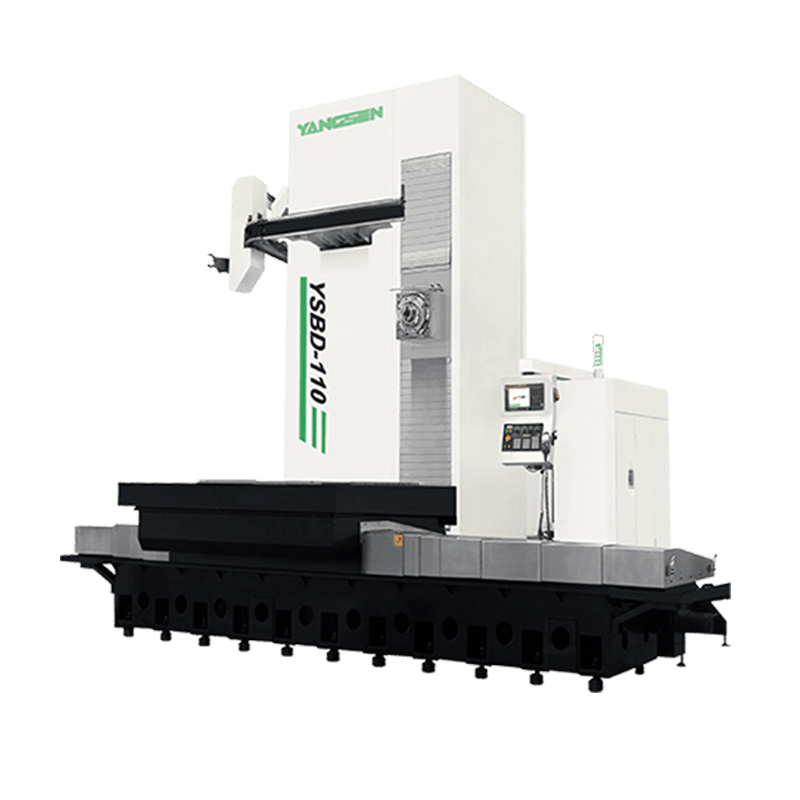
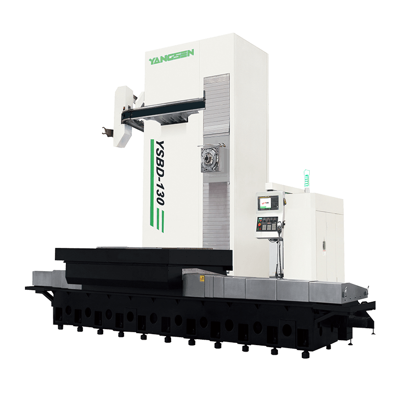
You can choose the suitable item from list below:
| Model | YSBD-110/5T | YSBD-110/6T | YSBD-110/8T | YSBD-130/8T | YSBD-130/15T | YSBD-130/20T |
| Table Size LxW mm | 1250x1250/5T | 1250x1500/6T | 1400x1600/8T | 1400x1600/8T | 1800x2200/8T | 2500x2500/25T |
| Spindel Diameter mm | D110 | D110 | D110 | D130 | D130 | D130 |
1. Comply with the general safety operating procedures for milling and boring workers. Wear labor protection articles as required.
2. Check whether the connection of the operating handle, switch, knob, clamp mechanism, and hydraulic piston is in the correct position, whether the operation is flexible, and whether the safety devices are complete and reliable.
3. Check whether there are obstacles within the effective operating range of each axis of the machine tool.
4. It is strictly forbidden to use the machine tool beyond its performance. Select the appropriate cutting speed and feed rate according to the workpiece material.
5. When loading and unloading heavy workpieces, a reasonable spreader and hoisting method must be selected according to the weight and shape of the workpiece.
6. When the spindle is rotating and moving, it is strictly forbidden to touch the spindle and the tool installed at the end of the spindle with your hands.
7. When changing the tool, you must stop the machine first, and then replace it after confirmation. When changing, you should pay attention to the damage of the blade.
8. It is forbidden to step on the guide rail surface and painted surface of the equipment or place objects on it. It is strictly forbidden to knock or straighten the workpiece on the workbench.
9. After inputting the processing program for a new workpiece, it is necessary to check the correctness of the program and simulate whether the running program is correct. Automatic cycle operation is not allowed without testing to prevent the machine from malfunctioning.
10. When using the flat-rotating radial tool post for cutting alone, the boring bar should be returned to the zero position first, and then in the MDA mode, use M43 to switch to the flat-rotating disc mode. If the U-axis needs to move, you must ensure the U-axis manual clamping device has been loosened.
11. When it is necessary to rotate the table (B axis) during work, it should be ensured that it will not touch other parts of the machine tool or other objects around the machine tool during rotation.
12. When the machine tool is running, it is forbidden to touch the surroundings of the rotating thread shaft, polished rod, spindle, and flat rotating disk, and the operator must not stay on the moving parts of the machine tool.
13. When the machine tool is running, the operator is not allowed to leave the job without authorization or entrust someone to watch it.
14. If there are abnormal phenomena and noises during the operation of the machine tool, stop the machine immediately, find out the cause, and deal with it in time.
15. When the headstock and worktable of the machine tool are at or close to the movement limit position, the operator shall not enter the following areas:
(1) Between the bottom surface of the spindle box and the bed;
(2) Between the boring shaft and the work;
(3) Between the boring shaft and the bed or the working table when it is extended;
(4) Between the worktable and the spindle box when it is moving;
(5) When the boring shaft rotates, between the rear tailpiece, the wall, and the fuel tank;
(6) Between the workbench and the front main column;
(7) Other areas that may cause extrusion;
16. When the machine tool is shut down, the table must be retracted to the middle position, the boring bar should be retracted, then the operating system should be exited, and finally, the power should be cut off.