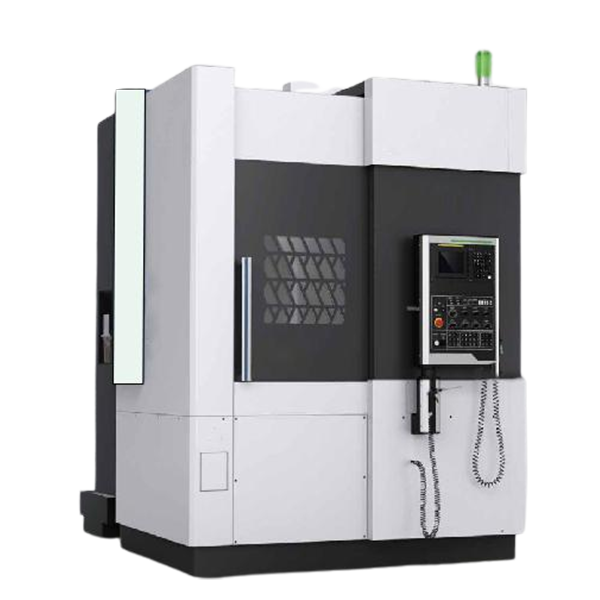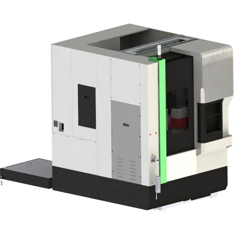
CNC Vertical Lathe Machine is a machining tool with a vertically oriented spindle, controlled by a computer numerical control (CNC) system. It is primarily used for high-precision turning of large, circular workpieces, including operations such as external turning, facing, and internal boring.
Max. X-axis Travel :
0~+1750mmMax. Z-axis Travel :
1400mmMax Workpieces Height :
2500mmMax Workpieces Weight :
16000kgApplication :
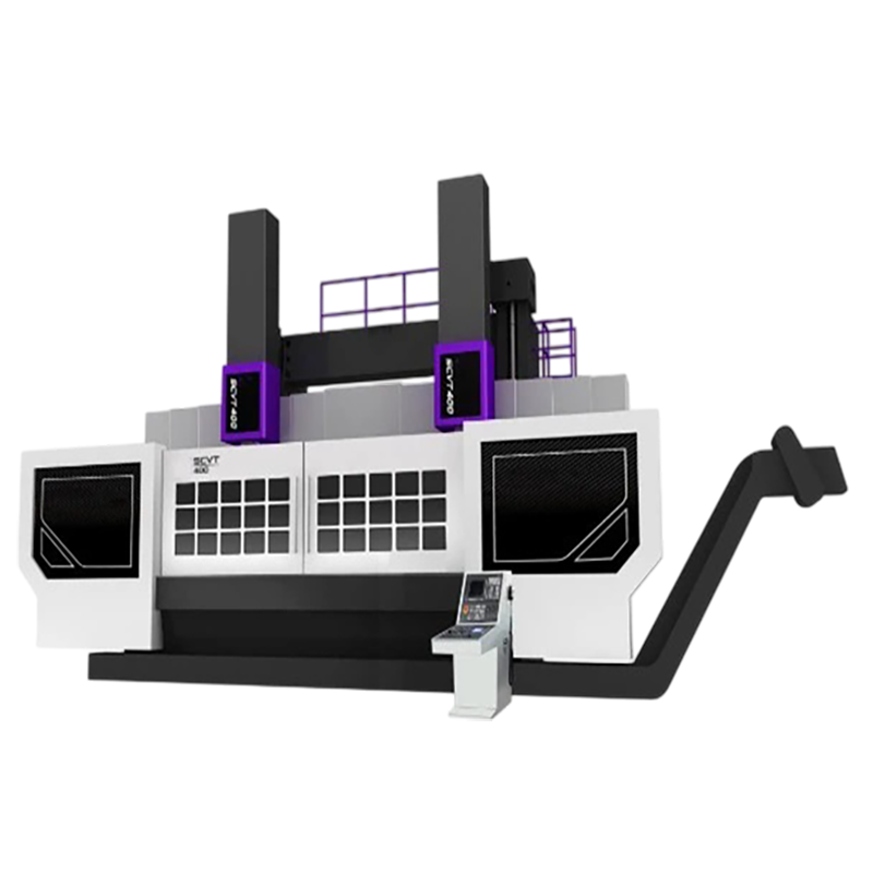
Power generation, shipbuilding, metallurgy, and mining.Main Structure of CNC Vertical Lathe Machine

1. This series of machine tools is used for carbide and ceramic cutting tools, and is used for rough and fine turning of inner and outer cylindrical surfaces, inner and outer conical surfaces, end surfaces, grooving and boring, and rotary surfaces of ferrous metals and some non-metallic parts.
2. The main transmission of the machine tool is driven by a DC motor, and the speed range of the workbench is realized through a two-speed spindle speed change mechanism.
3. The machine tool is a frame structure composed of left and right columns, connecting beams, crossbeams, working bases and other components. The structure is rigid and has a large load-bearing capacity. The crossbeam clamping mechanism is a multi-station hydraulic locking device, and its operation is stable and reliable.
4. The feed tool holder of the machine tool adopts a CNC single tool holder structure. The machine tool tool holder slide horizontal movement X axis and the ram vertical movement Z axis are both driven by servo motors, and the ball screw is driven by a high-precision fixed ratio gear pair to realize tool holder feeding and rapid movement.
5. The workbench is a thermally symmetrical structure. The worktable spindle uses high-precision adjustable radial clearance double-row short cylindrical roller bearings for centering. The shaft uses constant-flow hydrostatic guide rails and is equipped with an oil temperature cooling device, which makes the worktable have the characteristics of high rotation accuracy, large load-bearing capacity, and small thermal deformation.
6. The horizontal guide rails of the vertical tool holder include hydrostatic unloading guide rails, rolling and sliding composite guide rails, and sliding guide rails. The vertical movement of the ram is a sliding guide rail.
Vertical Tool Holder

The left and right vertical tool rests are composed of a beam slide, a rotary slide, and a ram. The left and right tool rests can move horizontally (X) on the beam. The left and right and vertical movements of the ram in the tool rest are driven by a FANUC AC servo motor, which is transmitted to the ball screw nut connected to the gears through a gear pair, so that the ram connected to the ball screw can move left and right (X) and vertically (Z), realizing the four-axis linkage of the left and right vertical tool rests X and Z, and realizing the processing of curved surfaces. The ram is a square steel ram, and the lower end of the ram is equipped with a tool holder, which is fixed to the lower end of the ram. The ram is a square steel ram.
Key Technology Parameters
| Project | unit | Specification | |
| Main parameters | Workbench diameter | mm | 2400 |
| Maximum rotation diameter | mm | 2800 | |
| Maximum turning diameter | mm | 2800 | |
| Maximum workpiece height | mm | 2500 | |
| Maximum workpiece weight | Kg | 16000 | |
| Maximum torque of the worktable | N.m | 63000 | |
| Main tooth | Spindle speed range | r/min | 1.5~80 |
| Wheel Box | |||
| Workbench speed change gear | block | Two-speed infinite | |
| Main motor output power | 30-minute rating | kW | 65 |
| Continuous Rating | kW | 55 | |
| Ram | Ram body cross-sectional dimensions | mm×mm | □240X240 |
| X 1 axis travel | mm | 0~+1750 | |
| X 2-axis travel | mm | -175 0 ~0 | |
| Z1 axis travel | mm | 1400 | |
| Z2 axis travel | mm | 1400 | |
| Knife holder | Square knife holder | 2 | |
| beam | Crossbeam travel | mm | 2000 |
| Feed speed | Cutting feed speed | mm/rev | 0.1 ~ 1000 mm / min |
| Rapid feed rate | mm/min | 6000 | |
| Tool holder | Double knife holder | 2 | |
| Turning tool bar size | mm×mm | 40×40 | |
| weight | Total weight of the machine tool | Kg | Approximately 49,300 |
| system | CNC device model | FANUC oi TF | |
| Machine tool appearance | Length × Width × Height | mm×mm×mm | 7800X4800X7400 |
| Main power supply | Voltage | V | AC380 |
| Voltage fluctuation range | -10 to +10% | ||
| frequency | Hz | 50 ±1 | |
| Total power | kW | 80 | |
| Total power supply includes | Main motor | kW | 55/65 |
| Hydraulic motor | kW | 2.2 | |
| Cooling pump motor | kW | 0.75 | |
| X1 /X2 axis servo motor | kW | 6 | |
| Z1 /X2 axis servo motor | kW | 6 | |
| Lifting motor | kW | 11 | |
| NC unit | KVA | 0.05 | |
| Control Panel | KVA | 0.02 | |
| Fan motor, fluorescent lamp, etc. | kW | 0.16 | |
| Chip conveyor motor | kW | 0.2 | |
| Hydraulic system pressure | Mpa | 5 | |
Tags :