The lathe machine presents itself as a complicated configuration of knobs, handles, and moving components when you approach it for the first time. Everything becomes understandable after grasping the functions of individual lathe machine components. The lathe machine operates through the synchronized operation of multiple components, which precisely transform metal and wood materials.
This article explains each critical component of the lathe machine and its operational mechanism while demonstrating its importance for everyday machining operations.
A lathe machine operates as a tool that spins your workpiece, and a cutting tool forms its shape. The machine conveys power to cut, along with drilling and turning, and facing operations on metals and wood, and plastics. The cutting tool remains stationary as the part spins around it. Rotation enables the machine to perform uniform shaping operations. Large industrial operations such as factories and repair stations utilize lathes as standard equipment.
Round shapes such as rods, bolts, and shafts require such tools for their production. The machine allows users to produce accurate threaded cuts and drill precise holes. No matter the operation, the lathe follows a simple principle, which states that rotation performs all necessary tasks.

All components of the lathe fulfill specific operational functions. A deeper knowledge of machine components allows users to get better results from their operations. The rapid setup process and elimination of expensive errors benefit from your knowledge of each part. Understanding the movements of machine parts allows users to maintain complete control over their cutting operations. The machine provides better safety protection when it is operating. You can resolve any problems more rapidly when they occur. Knowledge about all components allows you to achieve better surface quality standards and narrower manufacturing specifications. Understanding each part of your machine allows you to develop into a better-skilled machinist.
Strong machines always originate from fundamental frameworks. The lathe is no different. A lathe performs best when its principal elements remain stable and properly aligned. The backbone of any lathe contains three essential structural parts divided into these sections for analysis.
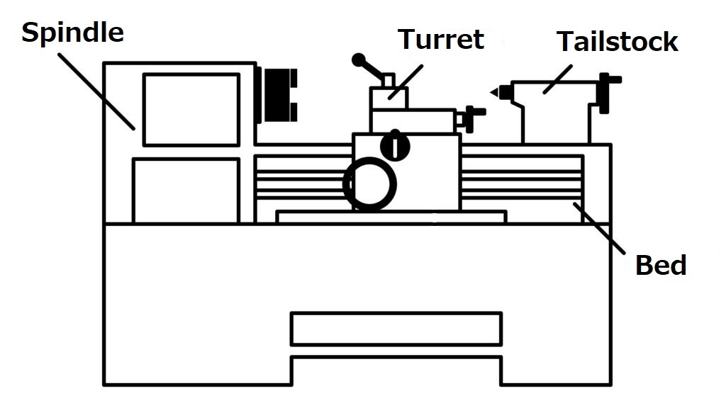
The bed is the lathe’s base. It holds everything together. The bed functions as the machine's main support. The bed extends across the lathe framework in a flat shape, with its construction from cast iron or steel material. Why? Under strong pressure, the bed must remain solid without any deformation. No bending. No twisting. The bed functions as an essential base that handles any heavy material while maintaining precise line-ups.
It also guides movement. The bed surface contains precision-machined ways that function as tracks for controlling smooth movement among other parts. The carriage tailstock, in line with the optional headstock, travels along the ways that guide its movement. Your metal cuts maintain their straightness thanks to the precise alignment of the bed. Any misalignment in the bed position will make your entire workpiece inaccurate. The bed functions as more than a support because it enables all precise cuts through unseen assistance.
The lathe operates on the principles that emerge from the headstock. Located on the bed end, the spindle receives its support from this fixture which also operates the rotating spindle mechanism. The gears, along with belts and the possible motor, operate inside the headstock. The coordinated operation between these components results in strong rotational power.
Most workers attach their workpieces through chucks or faceplates on this mounting part. The spindle activates to spin your workpiece after it becomes securely locked within the system. That’s how the cutting begins. Adjustment of machine speeds is possible through the headstock controls, allowing users to work with different materials and tools.
The strength of the headstock reduces machine vibration, which produces cleaner cuts and better machine finishing quality. That’s why it’s built tough. This part needs to withstand cutting pressure so it can maintain the ideal rotation of your workpiece.
The tailstock locates itself at the furthest end of the bed structure. Supportive functions are essential, although they lack noticeable glamour. The tool position depends on the workpiece length, and you adjust it accordingly. Then you lock it down tight.
The tailstock contains a spindle, also known as a quill, that extends and retracts from its setting. You can install the center on this location for supporting extended parts. The spinning pieces remain stable without flexing or wobbling during rotation because of this tool. Long, thin shafts require proper suppor,t which becomes essential during their machining process.
Essentially, the tailstock provides support functions along with other important features. The device enables users to install either drill chucks or boring tools for operation. You can use this function to produce straight holes exactly at the midsection of your workpiece. A tailstock alignment with the headstock produces centered and neat results.

The tool handling system becomes the center of cutting performances. These components determine the movement of your cutting tool together with its support system and its capacity to form shapes in a rotating workpiece.
Your tool requires the carriage to function as its transportation system. The holder carries the cutting tool as it proceeds along the bed. The tool moves in a direction that runs along the same plane as the rotating workpiece. The complete surface remains straight and even through this process.
The bed contains ways that guide its smooth movement from one position to another. The device has two options for movement control that can be activated either through manual handwheels or powered by machine systems. Both the cross slide and the compound rest are found within the carriage. The platform functions as the main supporter for every cutting operation performed on it. Your tool requires the carriage as its movement vector through the machine tool.
From its position at the bed, the cross slide enables your tool to move in left and right directions. The additional control feature rests on top of the carriage. You will use this function when working on side part shapes and diameter formation.
The depth of your slicing operation can be altered with high accuracy. A single handwheel rotation makes the tool travel only a tiny distance. The combination of these operations produces both accurate dimensions together with precise finish quality. To achieve precise cuts the cross slide provides the solution.
The compound rest allows you to perform angled operations. The compound rest attaches to the cross slide and permits adjustable angular rotation. Locking the device at a particular angle enables you to execute exact tapered cuts.
Need to thread? The compound rest enables you to create conical and beveled shapes. This is the tool for that. You can manually operate the compound rest because it moves by manual gestures. The device works optimally for creating angled cuts when a simple back-and-forth motion cannot be used.
The first step before cutting anything involves tight material grasping. Your material remains steady at the center of the lathe through its holding parts while rotating.
A majority of work materials fit inside the chuck. The spindle that belongs to the headstock receives this attachment. The material rests in the chuck when it spins. Three-jaw chuck models are the most frequently used tool for this purpose. It centers round objects automatically. A manual adjustment on the 4-jaw chuck becomes necessary for secure holding of square or odd-shaped materials.
A firm grip of the chuck ensures safe material cutting operations. Your cut will become inaccurate whenever the workpiece starts moving during operation. So before every job, double-check your chuck’s grip.
Some parts cannot be accommodated within a chuck. The faceplate functions as a solution to this problem. The faceplate establishes a large flat connection with the spindle for attachment. You mount your part directly to the faceplate through bolt or clamp tools.
The faceplate offers an ideal solution to cut irregularly shaped components that exceed regular chuck capacity. A faceplate enables you to customize your clamping options better than other tools. Whatever you attach to the faceplate needs to maintain stable equilibrium. The spinning motion becomes disturbed when any component possesses an uneven surface.
Long workpieces require additional stability because they exceed the natural length that the spindle support can handle. The machine centers exist to provide this support. The workpiece supports can position themselves on opposite ends: one inside the headstock and the other in the tailstock. The workpiece rests between the two points that the centers provide.
The support system protects long shafts from both bending and vibration motion. The tool will perform its cutting operation without causing any movement or bending of the part when you position it this way. The method represents an efficient solution to handle large or thin pieces.
The power of a lathe machine depends entirely on its motion system functions. The machine parts unite to create both rotational motion and precise tool position for manufacturing operations. The power behind your cutting operations needs examination.
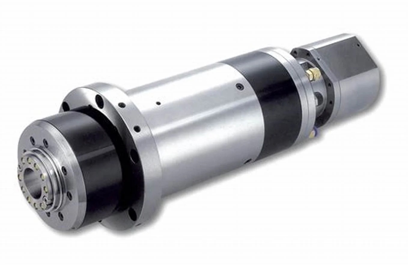
A workpiece rotates by means of the spindle mechanism. The structure occupies position inside the headstock where it links to the chuck or faceplate. After starting its operation it rotates based on the adjustment settings you choose.
The spindle receives built-in strength for enduring mechanical stress. The system operates steadily during high-speed operation to produce precise cutting results.
Without it, nothing moves. The basic movement required for turning operations powers every single turning operation. A spindle operating without vibrations produces resulting cuts that are both accurate and smooth.

You gain speed control of the spindle through the gearbox control mechanism. The mechanism within contains elements that adjust speed performance according to your intended cutting operations. When dealing with challenging materials you need additional torque. Choose a lower speed. To process soft materials you must select a faster rotor speed. Shift it higher.
Adjust the gearbox settings according to the tool type, together with the dimensions of the part material. It’s like the gears in a car. Smooth cutting depends on the right combination of speed and force. The gearbox enables quick job adaptation by the machine.
The two parts direct your cutting tool to traverse the workpiece. The threading process depends on the lead screw function. The lead screw produces exact and uniform threads through synchronized motion of the carriage relative to the spindle.
The feed rod operates as the system that maintains standard tool insertion. Through its functionality, the gearbox drives both carriages and cross slides to produce straight, even cuts. Both work through gears and couplings. The tool moves smoothly across the part when you activate the mechanism. Using this method enables you to achieve precise cuts through automated force.
All lathes require guidance mechanisms for adjusting their movements. The production tools allow operators to manually control the speed and path as well as the extent of each cutting operation.
The carriage features an apron positioned at its foremost area. A tool movement control system resides on the front section of the lathe. Operating the apron enables you to activate the lead screw or feed rod. The system incorporates both levers together with clutch components.
Most motion control activities occur at this point. When you need to activate tool feeding you should start this process. Use the apron. Want to stop it instantly? The apron does that too. This mechanical feature enables the tool movement through the generated power system.
The feed selector functions as your device selection control to determine tool movement directions. Users have the option to enable movement along the bed axis through longitudinal feed and movement across the bed through cross-feed. This tiny device produces significant operational effects in its system.
Maintenance of the job requires periodic changes between different feed directions. The tool provides instant and simple control to change machine directions. The system is required for threading operations and boring and cutting tasks.
Through the handwheels, you can control the lathe machine by hand. Through your hand movements, you operate the handwheels which control movements of the carriage as well as the cross slide and compound rest. The machine contains distinct wheels that control individual operational directions.
They’re ideal for fine adjustments. Using handwheels, you can easily achieve exact positioning when establishing a cut or finishing particular details. The mechanical movements of the machine and your hand movements match directly.
|
Component |
Function in Lathe Machining |
|
Bed |
Provides structural foundation; maintains alignment of headstock, tailstock, and carriage |
|
Headstock |
Houses spindle and gear mechanisms; transmits rotational motion to the workpiece |
|
Spindle |
Main rotating element; holds and drives the workpiece through the chuck or faceplate |
|
Tailstock |
Supports the free end of long workpieces; accommodates tools like drills or live centers |
|
Carriage |
Supports and moves the cutting tool along the longitudinal axis during turning operations |
|
Cross Slide |
Enables precise transverse movement of the tool; essential for facing and internal turning |
|
Compound Rest |
Allows angular tool positioning; used for taper turning and fine tool adjustments |
|
Chuck |
Secures the workpiece on the spindle; ensures accurate concentric rotation |
|
Faceplate |
Used to mount irregular or oversized workpieces not suitable for chucks |
|
Centers |
Provides axial support; minimizes deflection when machining long or slender workpieces |
|
Gearbox |
Offers variable speed control; transmits torque through selectable gear ratios |
|
Lead Screw |
Drives carriage for threading operations; ensures synchronized movement with the spindle |
|
Feed Rod |
Transfers power to the carriage and cross slide for automated feed operations |
|
Apron |
Houses feed controls and mechanisms to engage lead screw or feed rod for carriage movement |
|
Feed Selector |
Selects type and direction of feed motion (longitudinal or cross); adjusts feed rate as needed |
|
Handwheels |
Manual input devices for fine control over tool position and alignment |
|
Chip Pan |
Collects swarf and debris during machining; helps maintain a clean and safe workspace |
|
Steady Rest |
Provides intermediate support for long shafts; minimizes vibration and bending during rotation |
|
Thread Dial Indicator |
Synchronizes carriage with spindle rotation; essential for accurate thread cutting in imperial units |
The lathe machine operates as a shaping instrument that spins materials such as metal, wood, and plastic through its cutting operation. The machine serves workshops and factories for making circular parts such as rods and shafts. Many essential interlinked parts operate as a single system to complete the machine's operations. The machine's base function is to provide support for this entire system. The headstock supports the spindle that rotates the workpiece, and the tailstock maintains the position of the other end. All cutting tool guidance comes from the cross slide and carriage, along with the compound rest. All material remains stationary during cutting through the use of a chuck, faceplate, or centers. All power and movement functions within the machine stem from the gearbox and lead screw and feed rod which control tool direction and speed. The process control features of the lathe include handwheels and the apron and feed selector. The complete understanding of these parts allows users to operate the lathe safely and produce precise cuts and high-quality outputs.